The effectiveness of a hydraulic puller is derived from the synergistic relationship between its robust mechanical frame and its powerful hydraulic actuation system. Each component is engineered to withstand and transmit high tensile forces safely and efficiently. Understanding the design and function of these individual parts—from the alloy steel arms to the precision hydraulic cylinder—provides insight into why a hydraulic puller can perform tasks impossible for manual tools. This analysis breaks down the tool into its primary assemblies, explaining the role of the pulling arms, the crossbeam, the hydraulic ram, and the pump system, and how they integrate to create a cohesive and powerful extraction unit. The discussion concludes by highlighting how this specific design philosophy enables the hydraulic puller to tackle demanding disassembly operations.
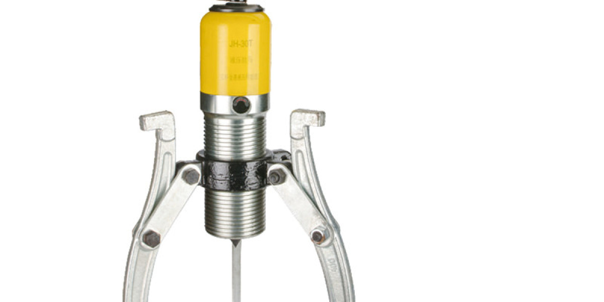
The mechanical skeleton of a hydraulic puller is formed by the pulling arms or legs and the crossbeam or yoke. These components are typically forged from high-strength alloy steel to resist bending under load. The arms are adjustable, often sliding through the crossbeam or attaching via slots, allowing the hydraulic puller to be configured for different component diameters. The ends of the arms feature claws or hooks designed to grip securely behind the workpiece. The crossbeam serves as the anchor point, distributing the reactive pulling force from the arms to the central hydraulic cylinder. Its design must prevent deflection, ensuring the force is applied evenly to avoid cocking the component on the shaft. This structural frame is what gives the hydraulic puller its rigidity and determines its mechanical reach and capacity.
At the heart of the system is the hydraulic actuator. This consists of a cylinder body, a piston, and a ram or forcing screw attached to the piston. In a common configuration for a two-arm hydraulic puller, the cylinder is mounted centrally through the crossbeam. When hydraulic pressure is applied, the piston moves, driving the ram forward. In this design, the ram pushes against the end of the shaft, while the crossbeam and arms are held stationary against the component. The reaction force pulls the component off the shaft. The hydraulic fluid, usually oil, provides incompressible power transfer and allows for precise control. A release valve on the cylinder or pump allows the operator to retract the piston and relieve pressure once the task is complete, a critical feature for resetting the hydraulic puller.
The power source is the hydraulic pump, which may be integrated into the puller frame or connected via a hose. Manual pumps use a lever to generate pressure, while air-over-hydraulic or electric pumps provide power-assisted operation for higher-capacity models. The pump draws fluid from a reservoir and directs it into the cylinder. A pressure gauge is frequently included, allowing the operator to monitor the force being applied by the hydraulic puller. This is important for both safety—avoiding overloading the tool—and for technique, as sometimes a sustained high pressure is more effective than an abrupt peak force. The hose connecting the pump to the cylinder must be rated for high pressure and resistant to abrasion and oil degradation.
The integration of these systems is what defines a capable hydraulic puller. The mechanical frame must be aligned so that the pulling force is applied directly along the axis of the shaft to prevent binding. The hydraulic system must provide smooth, controllable force without leaks. Accessories like various jaw sets, extensions, and adaptors increase the versatility of a single hydraulic puller frame.
The hydraulic puller is a purpose-built fusion of structural and fluid power engineering. Its design is not arbitrary; every element, from the thickness of the crossbeam to the bore of the hydraulic cylinder, is calculated to manage specific stress levels. This deliberate engineering allows the tool to apply forces ranging from a few tons to several hundred tons in larger industrial models. Therefore, selecting and using a hydraulic puller effectively requires an appreciation of both its mechanical setup and its hydraulic operation. A well-maintained hydraulic puller, with intact structural components and a leak-free hydraulic system, represents a long-term investment in safe, efficient, and reliable mechanical disassembly capability.
Ubicación del Autor
London, Reino Unido